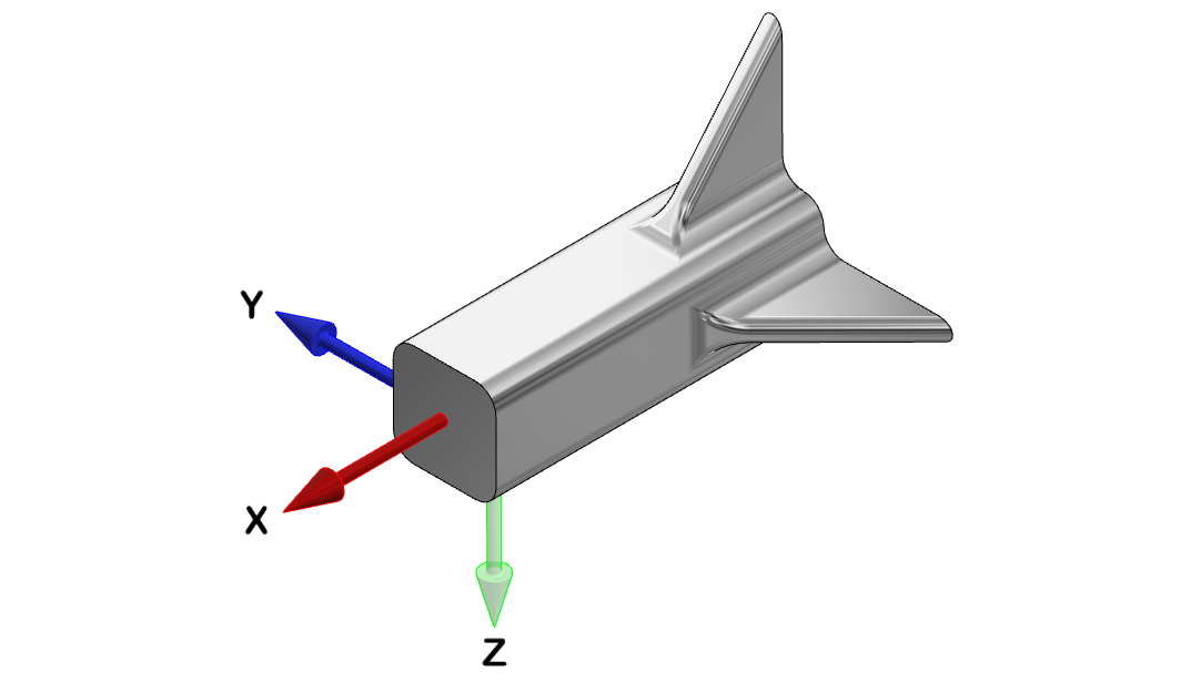
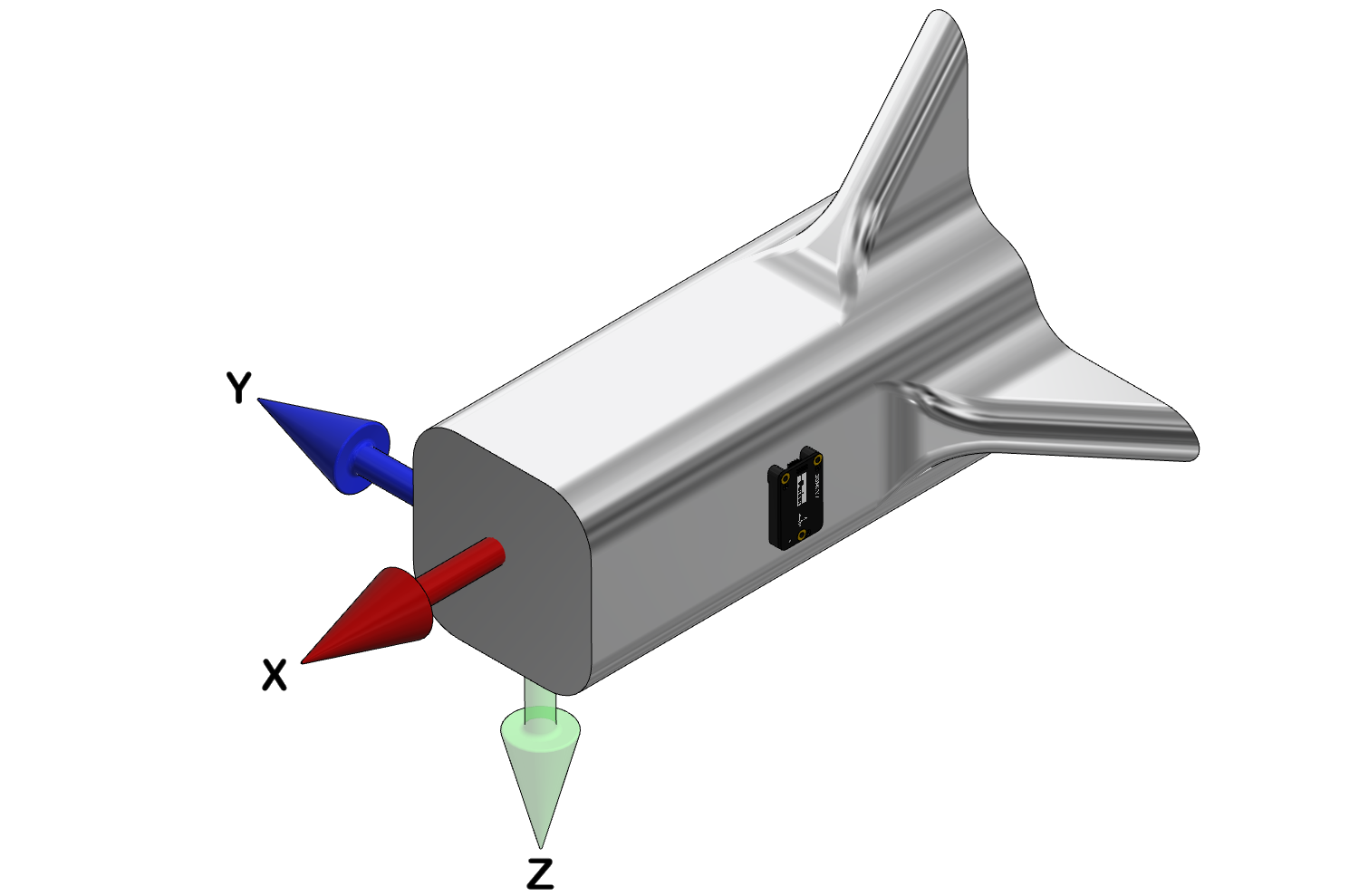
Vehicle Frame
The image below defines the following vehicle coordinate frame: the x-axis points in the forward direction, the y-axis points out the right-hand side of the vehicle, and the z-axis points down.
Transformation to Vehicle Frame
The 3DM-CV7 provides commands that define an orientation transformation that mathematically aligns the 3DM-CV7 sensing axes with the vehicle axes. These commands are useful when the sensor cannot be mounted in the same location or orientation as the desired reference point on the vehicle frame.
The transformation is expressed as a rotation from the sensor frame to the vehicle frame. The transform can be applied in either Euler angles using Sensor to Vehicle Frame Transformation Euler (0x0C,0x31) or with a direction cosine matrix using Sensor to Vehicle Frame Transformation Direction Cosine Matrix (0x0C,0x33).
|
IMPORTANT: Transforms in Euler angles must be achieved by applying rotations around the sensor axes in the following order (starting with the sensor oriented in the vehicle frame and ending in its actual mounting orientation): yaw (z-axis), pitch (y-axis), and roll (x-axis). A positive rotation around an axis is defined by the right hand rule. The fingers curl in the positive direction. |

|
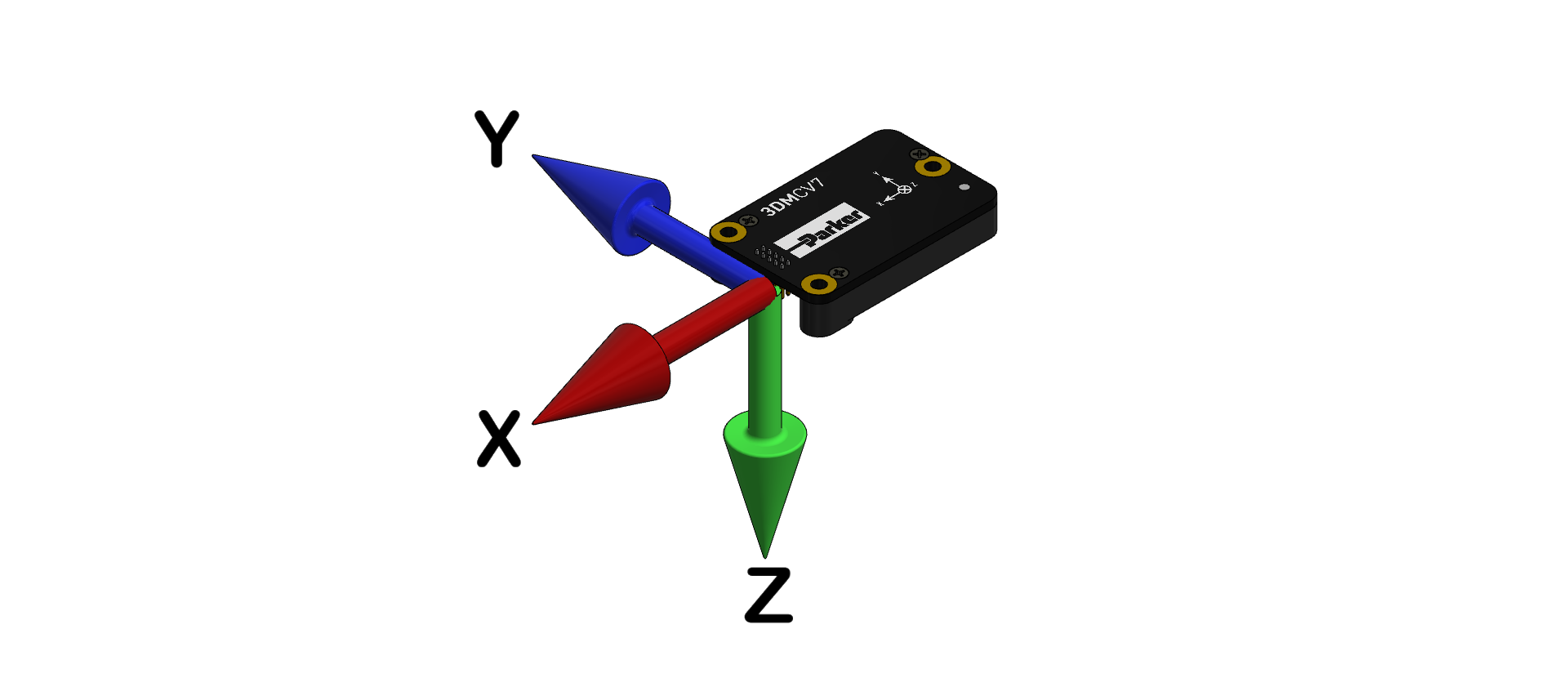
The following examples illustrate how to apply a transform using both sensor to vehicle transform commands. The Sensor Frame is shown in the diagram below.
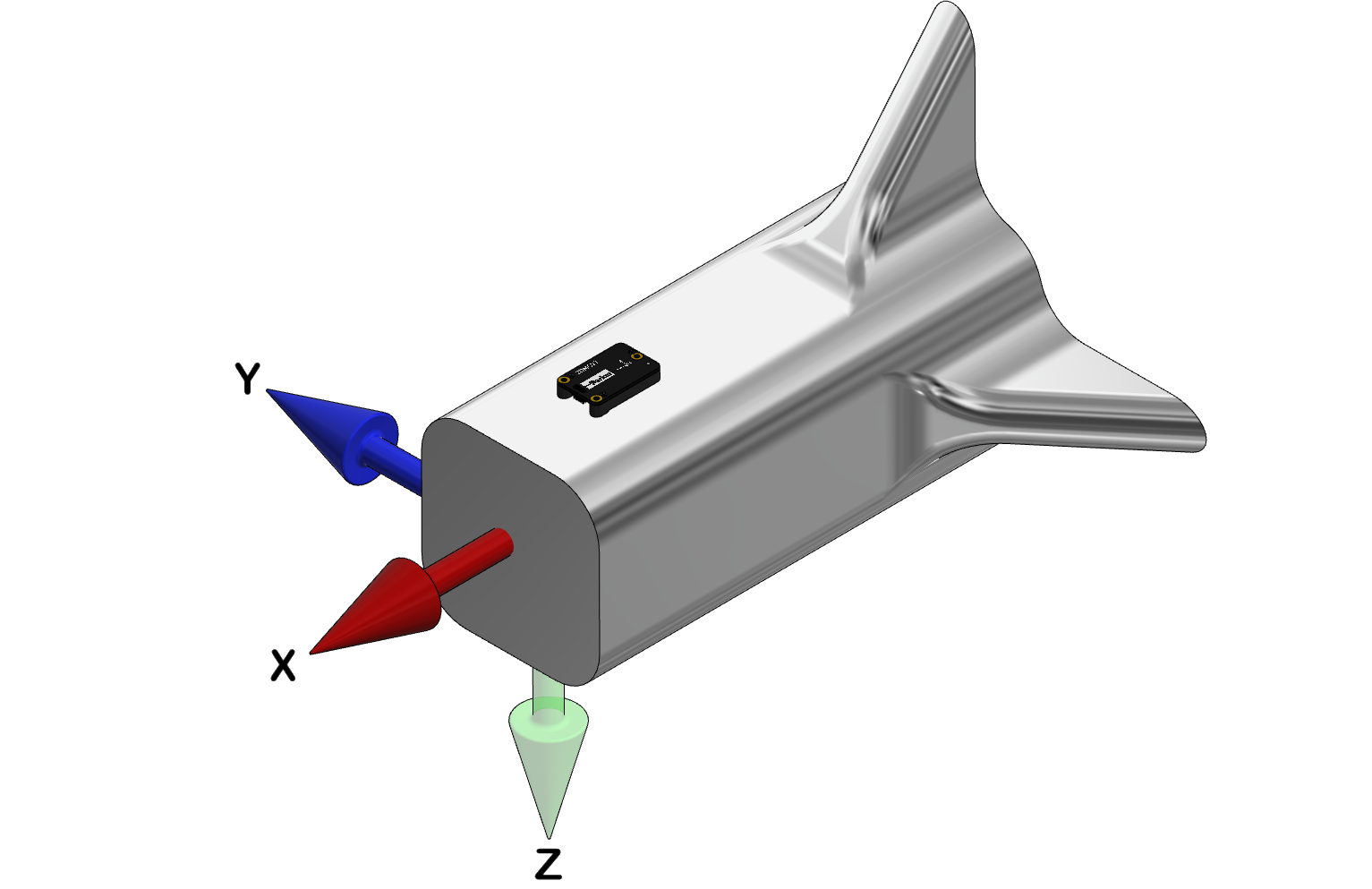
Example 1
In this example, the sensor frame is aligned with the vehicle frame. No transform has to be applied.
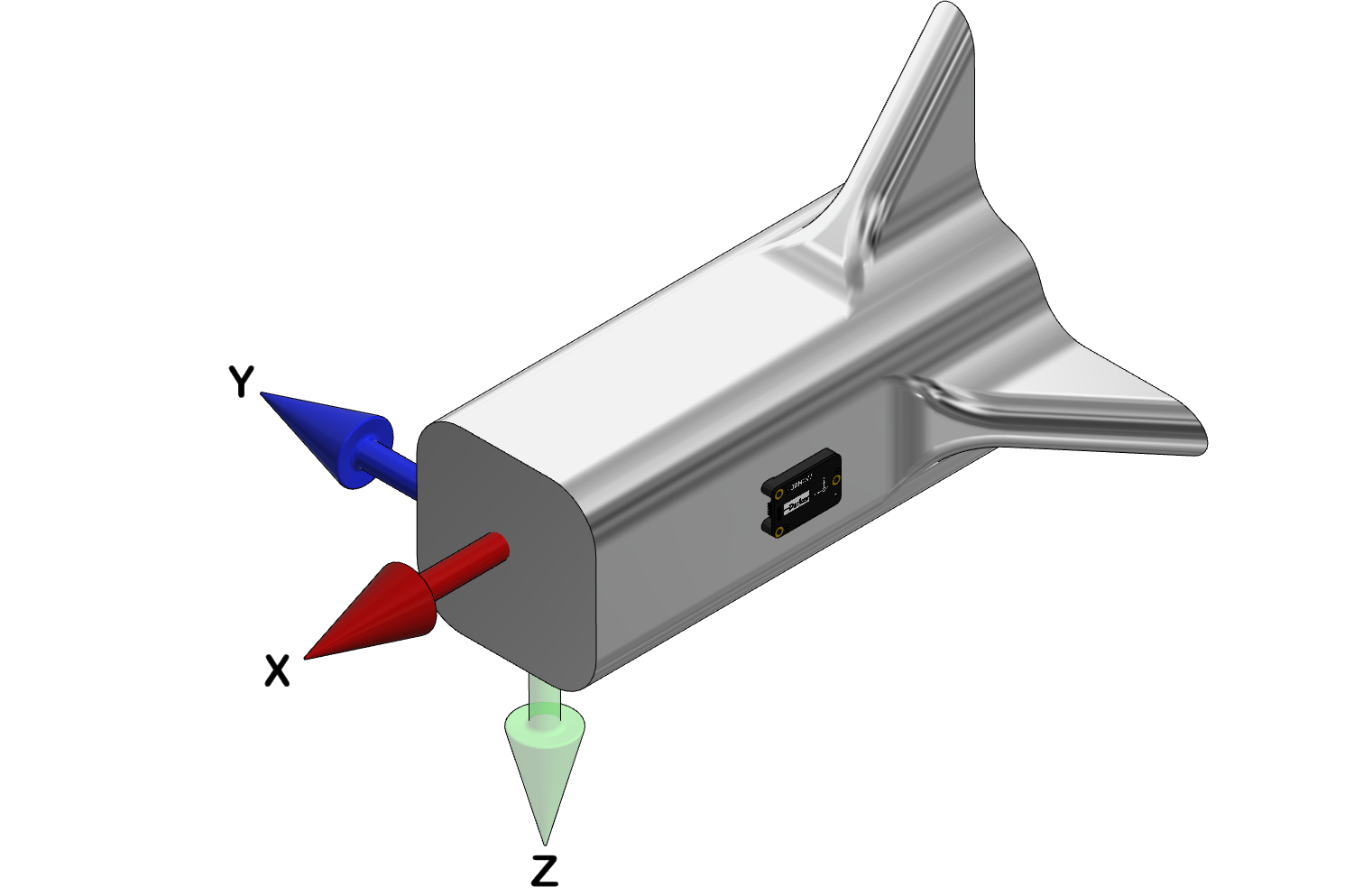
Example 2
In this example, the transform can be applied without a rotation around the sensor's yaw or pitch axes. A -90 degree (-1.5708 radian) rotation around the sensor's roll axis completes the transform.
|
Sensor to Vehicle Frame Transformation Euler (0x0C,0x31) Command Parameters |
Values | Units |
|---|---|---|
| Roll | -1.5708 | radians |
| Pitch | 0 | |
| Yaw | 0 |
| Sensor to Vehicle Frame Transformation Direction Cosine Matrix (0x0C,0x33) Command Parameters in Row Major Order (as required) | |||||||||
|---|---|---|---|---|---|---|---|---|---|
| Row, Col | 1,1 | 1,2 | 1,3 | 2,1 | 2,2 | 2,3 | 3,1 | 3,2 | 3,3 |
| Value | 1.0 | 0.0 | 0.0 | 0.0 | 0.0 | 1.0 | 0.0 | -1.0 | 0.0 |
Example 3
In this example, the transform is performed by first applying a +90 degree (+1.5708 radian) rotation around the sensor's yaw axis, followed by +90 degree (+1.5708 radian) rotation around the sensor's pitch axis. No rotation around the sensor's roll axis is required.
|
Sensor to Vehicle Frame Transformation Euler (0x0C,0x31) Command Parameters |
Values | Units |
|---|---|---|
| Roll | 0 | radians |
| Pitch | 1.5708 | |
| Yaw | 1.5708 |
| Sensor to Vehicle Frame Transformation Direction Cosine Matrix (0x0C,0x33) Command Parameters in Row Major Order (as required) | |||||||||
|---|---|---|---|---|---|---|---|---|---|
| Row, Col | 1,1 | 1,2 | 1,3 | 2,1 | 2,2 | 2,3 | 3,1 | 3,2 | 3,3 |
| Value | 0.0 | -1.0 | 0.0 | 0.0 | 0.0 | 1.0 | -1.0 | 0.0 | 0.0 |